 TimberVolt Platform · Field Operator's Guide
 Stage 1 R&D · Field Manual
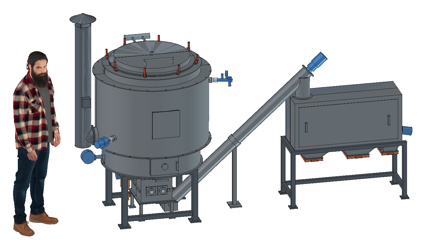
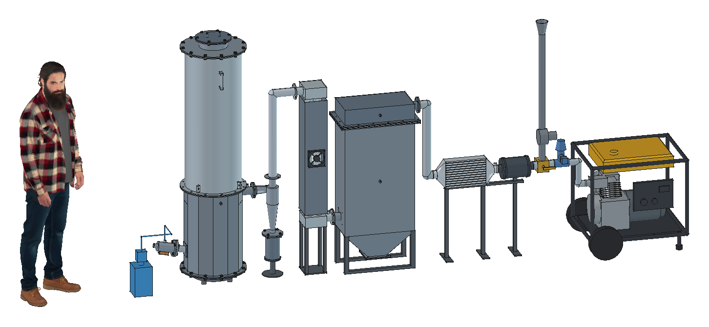
Field Operating Manual for TimberKiln 25 (Hydronic Cordwood Pyrolysis Retort & Sealed Mini-Crusher) and TimberGen 5 (5.0 kW Charcoal 48V DC Resilience Charger)
CO_Loop relay (hard kill ≥ 35 ppm) and always wear a calibrated personal CO monitor.T_retort > 100 °C; hot charcoal spontaneously reignites in air.~1.5 bar loop pressure and an unobstructed 3.0 bar safety relief discharge line before lighting kindling.
1" NPT hoses connected to thermal storage, P_glycol ≈ 1.5 bar, T_glycol_out < 40 °C, 3.0 bar PRV unobstructed.12V bus (controls, V_air_sec, Pump_glycol, stack solenoid) and 48V bus (crusher, trommel, micro-cyclone).100–120 kg split cordwood (300–500 mm length, 15–25% moisture, 30% max) plus dry kindling bundle.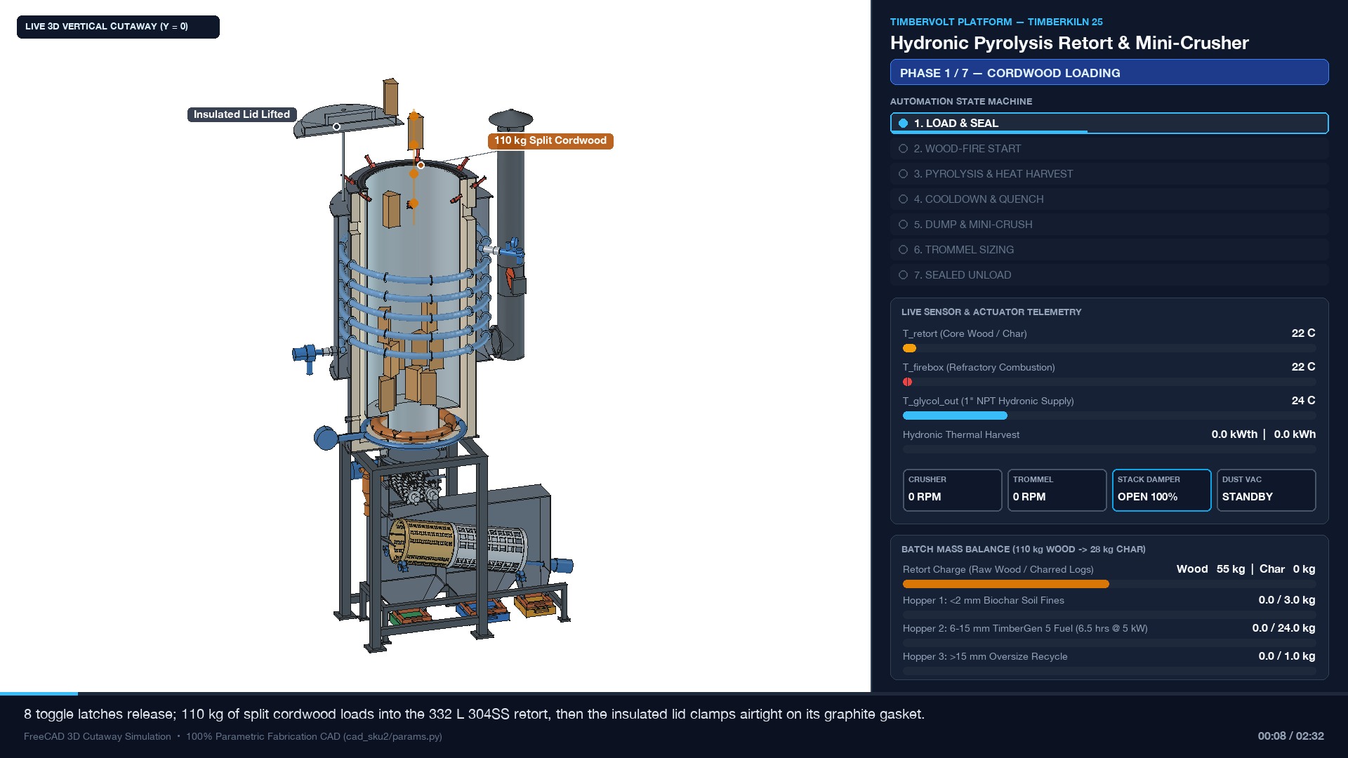
640 mm OD upper clamp flange.480 mm T_retort Type-K Inconel thermowell hanging beneath the dome.550 mm ID × 1,400 mm H (332 L) 304SS retort core, leaving ~50 mm headspace below the top rim.4× 2" stainless downcomers.
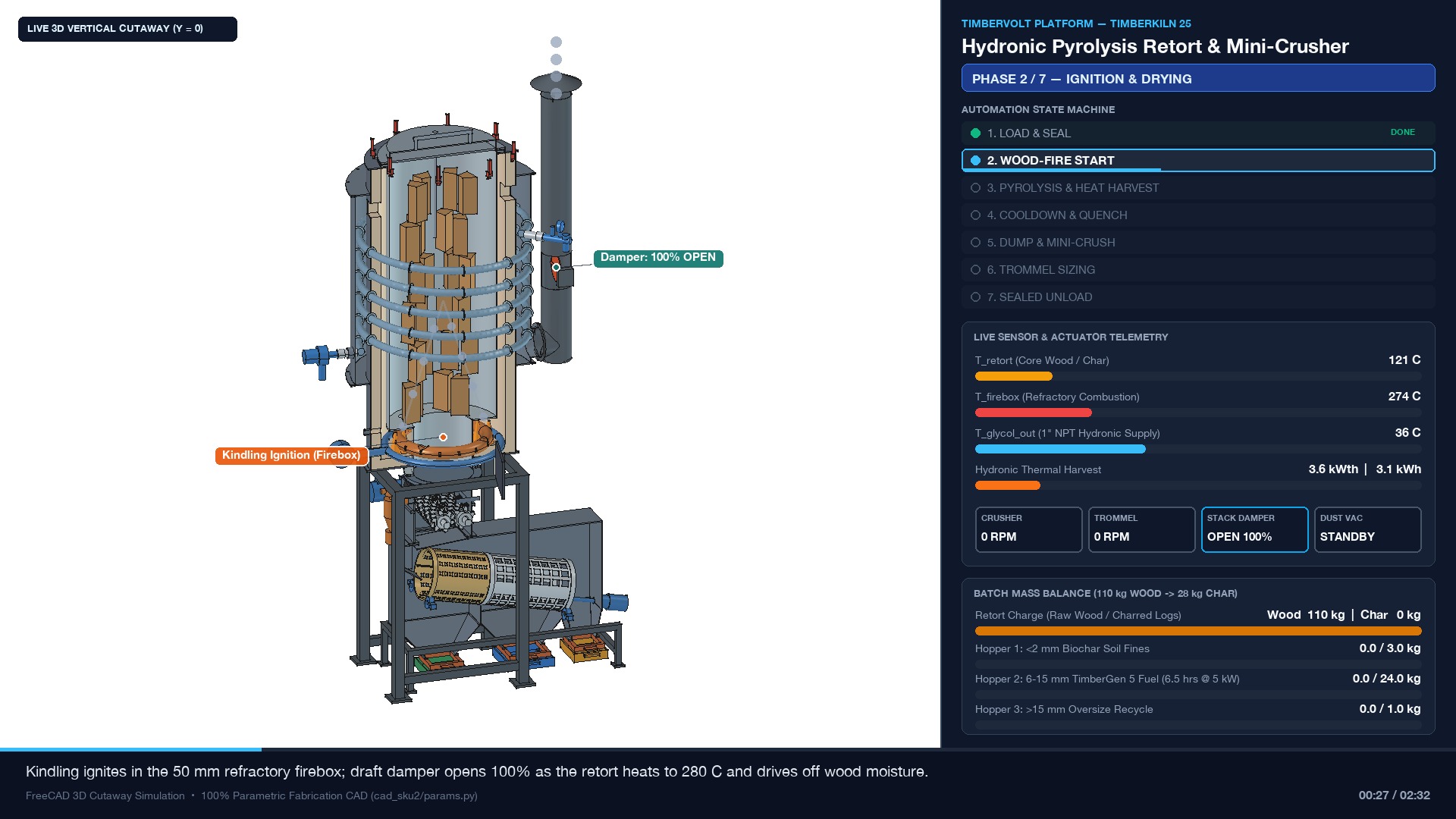
150 mm stack butterfly damper rotates to 100% OPEN.-Y Kindling Start Door on the 750 mm OD outer firebox, place dry kindling and small splits on the lower 50 mm refractory floor, light cleanly, and close the door with its rotary draft wheel open.600–700 °C, T_retort rises through 150–280 °C while moisture steams off through the 4× 2" downcomers and vents up the stack. Pump_glycol starts low-speed circulation above 45 °C.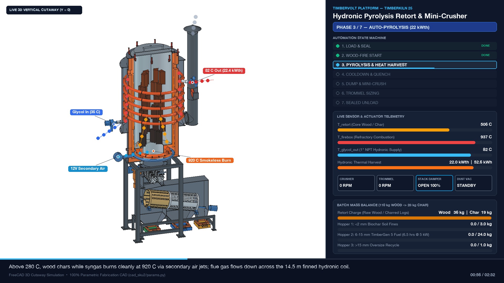
T_retort > 280 °C, pyrolytic wood gas and tars surge downward through the 4× 2" downcomers into the slotted toroidal burner ring. Confirm Flame_UV reads active flame (auto-igniter triggers automatically if flame drops) and close the kindling door's primary draft wheel.V_air_sec 12V PWM secondary air blower to hold T_firebox = 800–1,000 °C for complete, smokeless tar destruction.14.5 m spiral-finned 304SS coil (2.8 m²), cooling to ~140 °C at the stack while Pump_glycol (15–35 L/min) holds ΔT = 20 K and 75–85 °C supply (18–25 kWth, 70–90 kWh per batch).T_glycol_out > 92 °C, the controller forces Pump_glycol to 100% into the thermal dump loop and throttles V_air_sec. Mechanical brass PRV relieves at 3.0 bar.
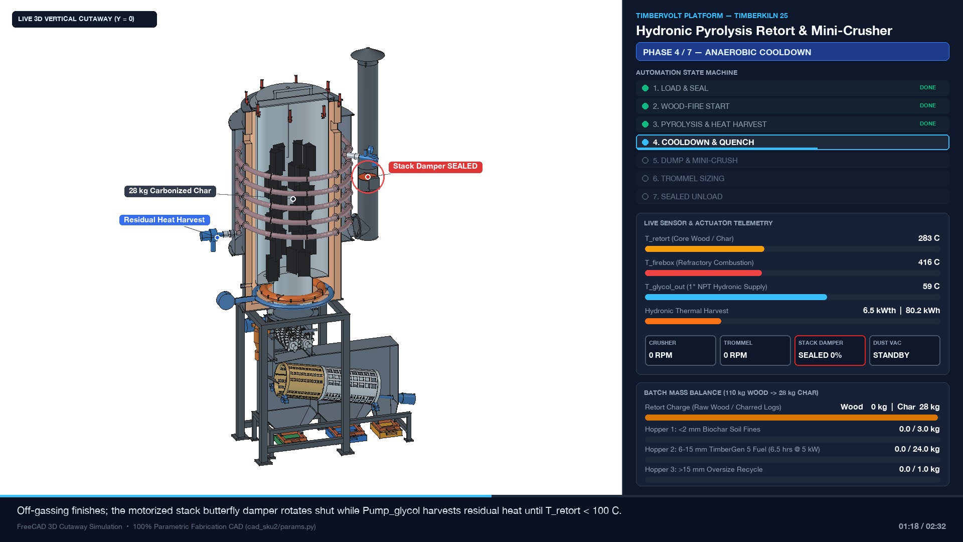
T_retort peaks at 550–650 °C) and T_firebox falls below 450 °C, the controller transitions automatically to COOLDOWN_QUENCH.150 mm motorized butterfly damper rotates to 0% SEALED and V_air_sec shuts off, starving the firebox of oxygen while keeping the 25–30 kg charcoal charge fully anaerobic.Pump_glycol circulating to harvest stored refractory heat until T_retort < 100 °C (target < 70 °C before dumping). Never open the dump gate above 100 °C.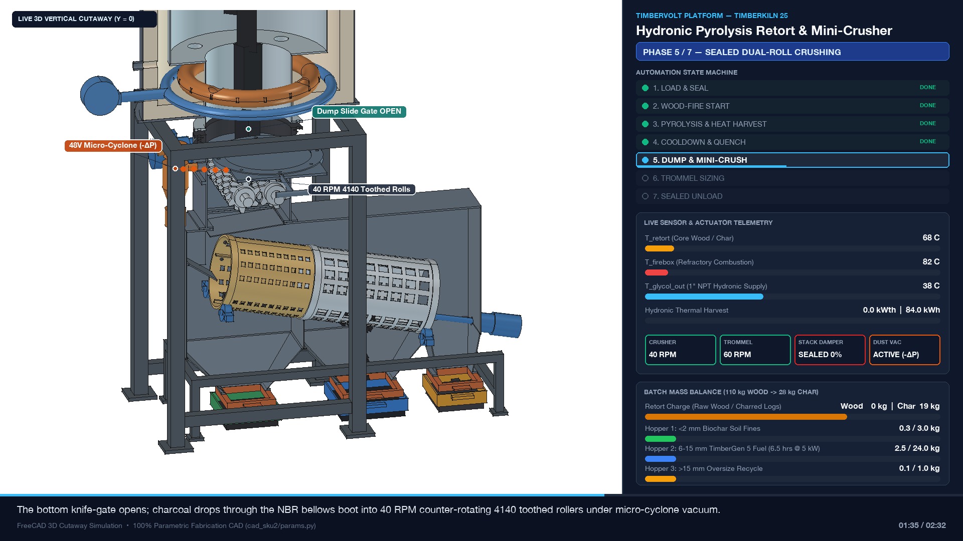
T_retort < 100 °C, check the corrugated NBR sealing boot clamps, and confirm the crusher bearing slide locks are set to 14 mm nominal nip gap (8–20 mm adjustable range).48V Micro-Cyclone Dust Extractor first (pulls negative pressure -ΔP via the Ø25 mm port to eliminate fugitive carbon dust).60 RPM Rotary Trommel and the 0.75 kW 48V DC Dual-Roll Crusher (30–45 RPM, 160 Nm torque; low RPM shears char cleanly with minimal dust).-Y T-handle of the Bottom Dump Slide Gate fully open (280 mm stroke); cooled char logs drop by gravity through the NBR boot into the interlocking Ø120 mm 4140 steel cutter teeth.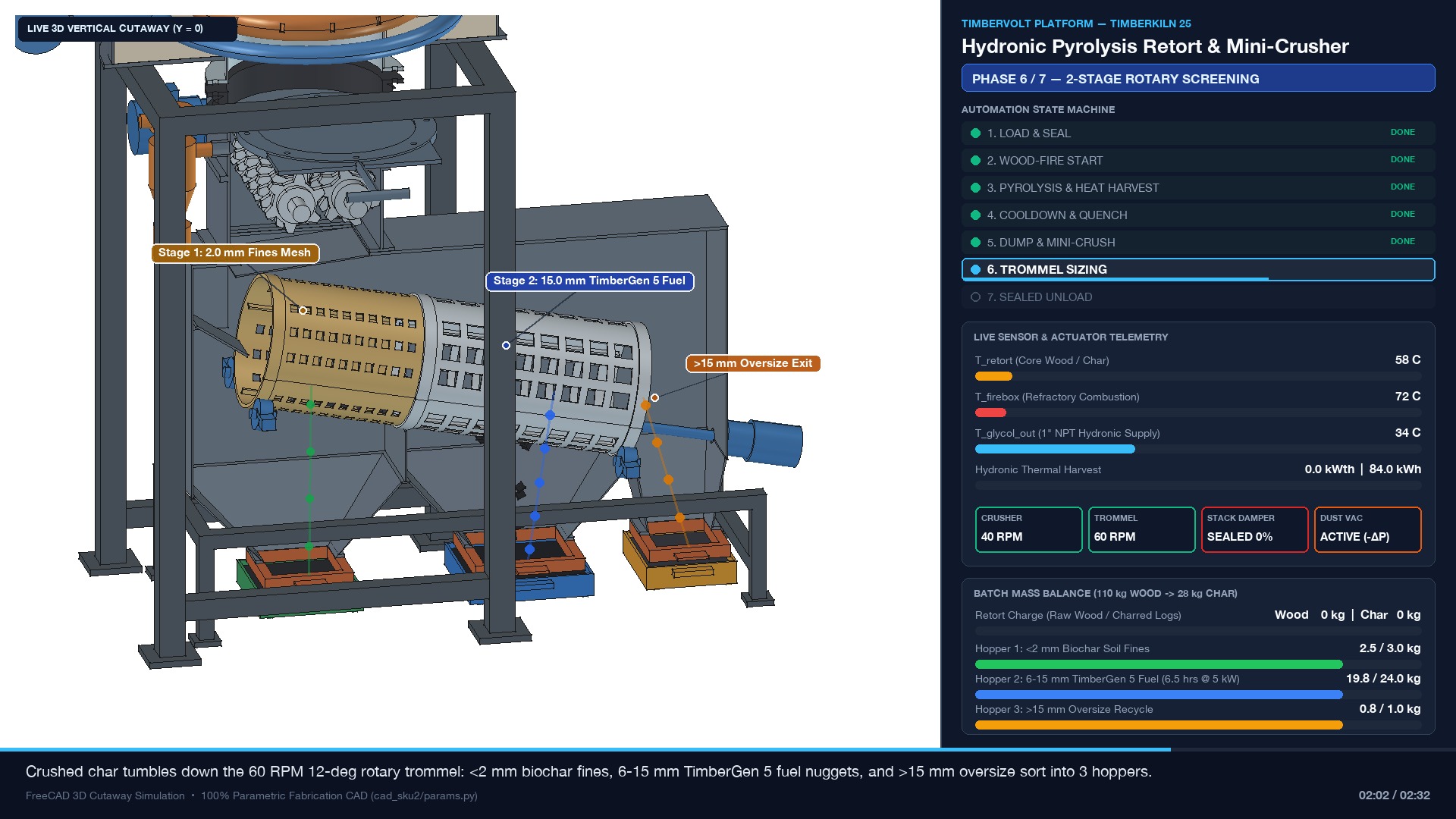
Ø250 × 750 mm drum inclined at 12° (60 RPM), automatically separating into three dust-sealed bottom hoppers:300 mm, 2.0 mm brass mesh) drops pure soil-replenishing biochar fines into the Green Tote.450 mm, 15.0 mm steel mesh) passes uniform TimberGen 5 engine nuggets into the Blue Fuel Tote.+X drum end into the Amber Return Bin for re-crushing on the next batch.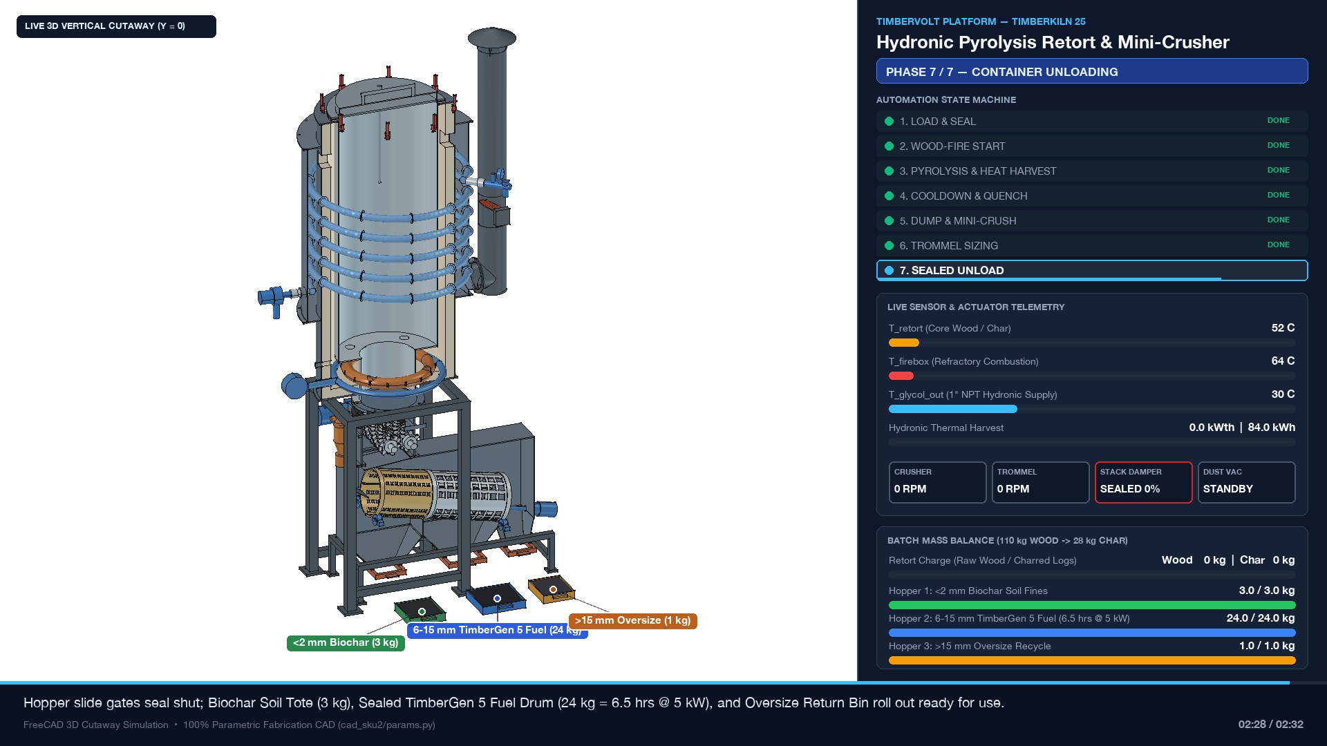
-Y handle seats flush.48V Micro-Cyclone.6–15 mm Fuel dry in a sealed 55-gal drum or load it straight into TimberGen 5 for ~6.0–6.5 hours of 5.0 kW DC power.
1. IDLE / PRE_CHECK)CO_Loop NC relay reads OK (< 35 ppm) on ESP32-S3 display.T_bag_in < 100 °C, cyclone catch pot empty & sealed, Stage 2 intercooler 1/4" NPT drain drained & CLOSED.P_h2o peristaltic tank with clean/distilled water (~6 L for a 6 hr run) to prevent evaporator scaling.48V LiFePO4 battery bank (< 95% SOC).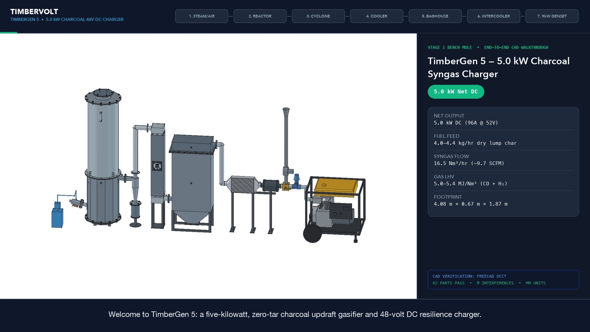
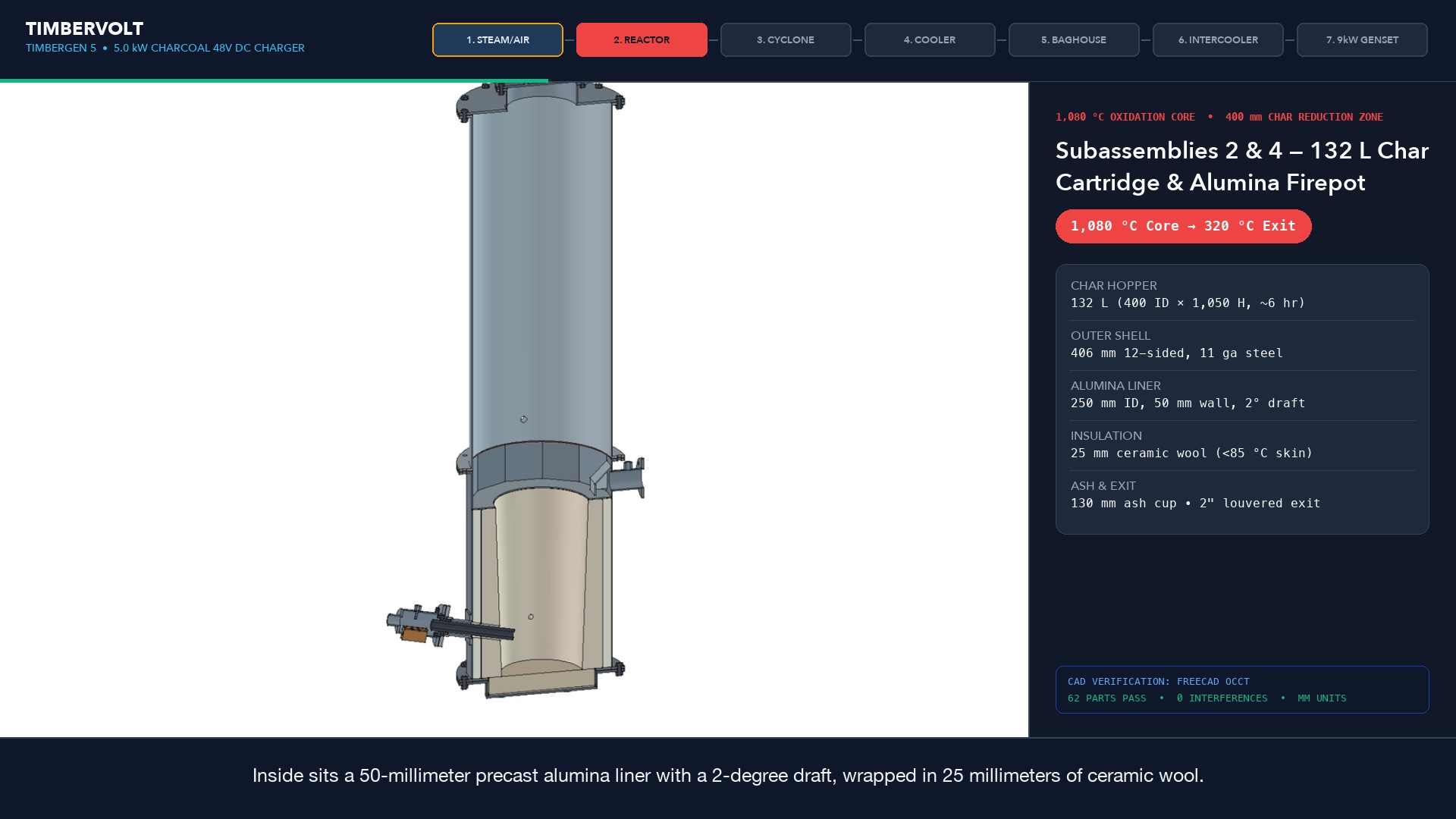
132 L 304SS Char Cartridge (400 mm ID × 1,050 mm H).6–15 mm charcoal nuggets from TimberKiln 25 into the hopper, filling both the 250 mm ID precast alumina firepot and upper cartridge (delivers ~6.0 hours at 4.0–4.4 kg/hr).V_air NEMA 17 stepper homes cleanly to 0° and the cartridge level switch shows FULL.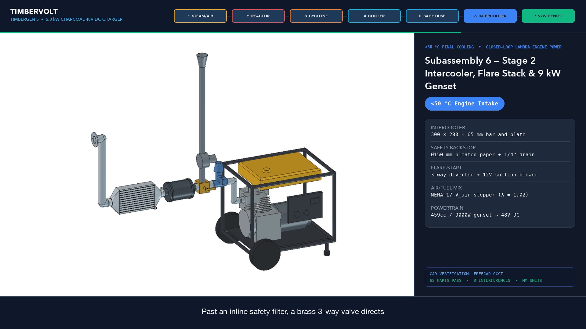
459cc engine intake).12V suction start blower ramps up, pulling air inward through the 12° 16 mm ID NBSiC ceramic nozzle.45 mm protruding nozzle tip glows bright orange.T_noz > 650 °C and Flare Temp > 450 °C, confirming a crisp, self-sustaining pale-blue/orange producer-gas flame atop the flare stack.> 450 °C) and clean reactor vacuum (dP_rx = 2.0–3.5 inH2O).V_air secondary air butterfly valve to 42% open for stoichiometric startup air/syngas mixing.12V start blower, and crank the genset starter (maximum 5 seconds per crank attempt).459cc genset catches and stabilizes at 3,600 RPM, verify steady vacuum (dP_rx = 2.8–4.0 inH2O) and cool engine intake temperature (T_eng_in < 55 °C).Flare Temp > 450 °C), verify V_air = 42%, and retry.
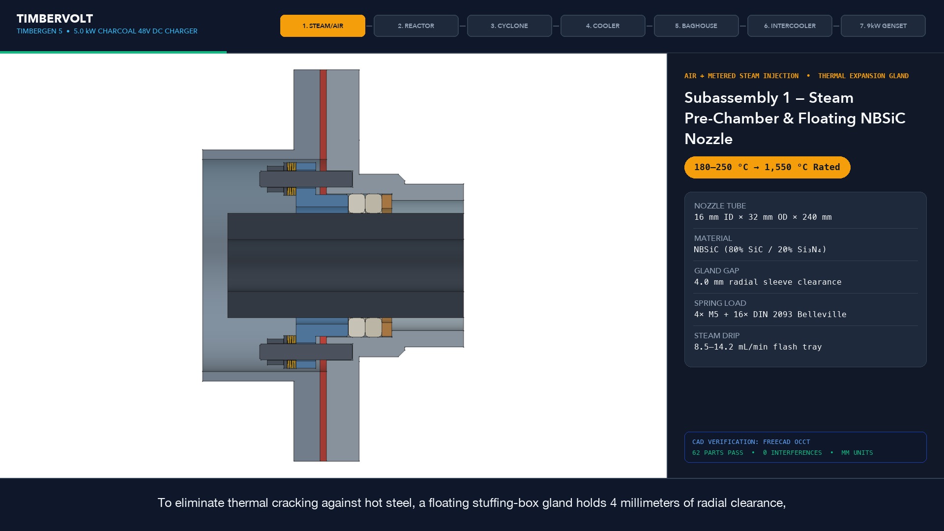
Lambda PID; the controller automatically trims the V_air stepper to hold λ = 1.02 (slightly lean for high brake thermal efficiency and ultra-low exhaust CO).30 A (~1.5 kW) warmup load until T_noz > 900 °C and the Steam Pre-Chamber evaporator plate exceeds 160 °C (180–250 °C nominal via exhaust heat or 60 W 48 V cartridge).P_h2o metered water drip (8.5–14.2 mL/min), flashing liquid water into dry steam inside the pre-chamber before entering the 16 mm NBSiC nozzle, boosting H2 energy content (5.0–5.4 MJ/Nm³) while holding core temperature cleanly at 1,000–1,150 °C without ash slagging.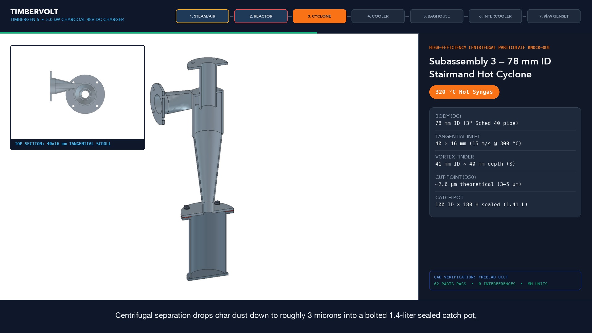
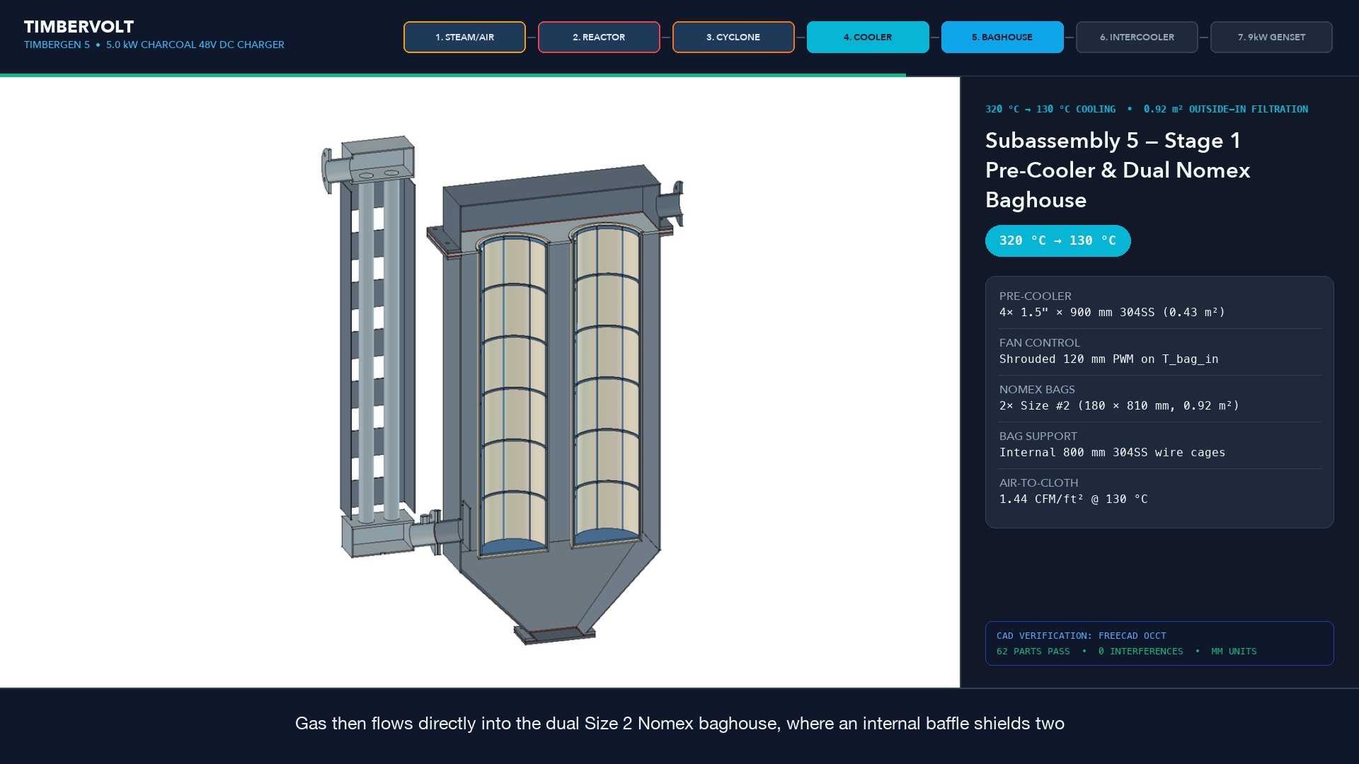
95–96 A @ 52 V DC (5.0 kW net electrical output).78 mm Stairmand Hot Cyclone (d50 ≈ 2.6 μm), Stage 1 4-Tube PWM Cooler (320 → 130 °C), Dual Size #2 Nomex Baghouse (120–140 °C, above dew point & below scorch), and Stage 2 Bar-and-Plate Intercooler (< 50 °C engine intake).132 L cartridge (~30 kWhe net DC delivered).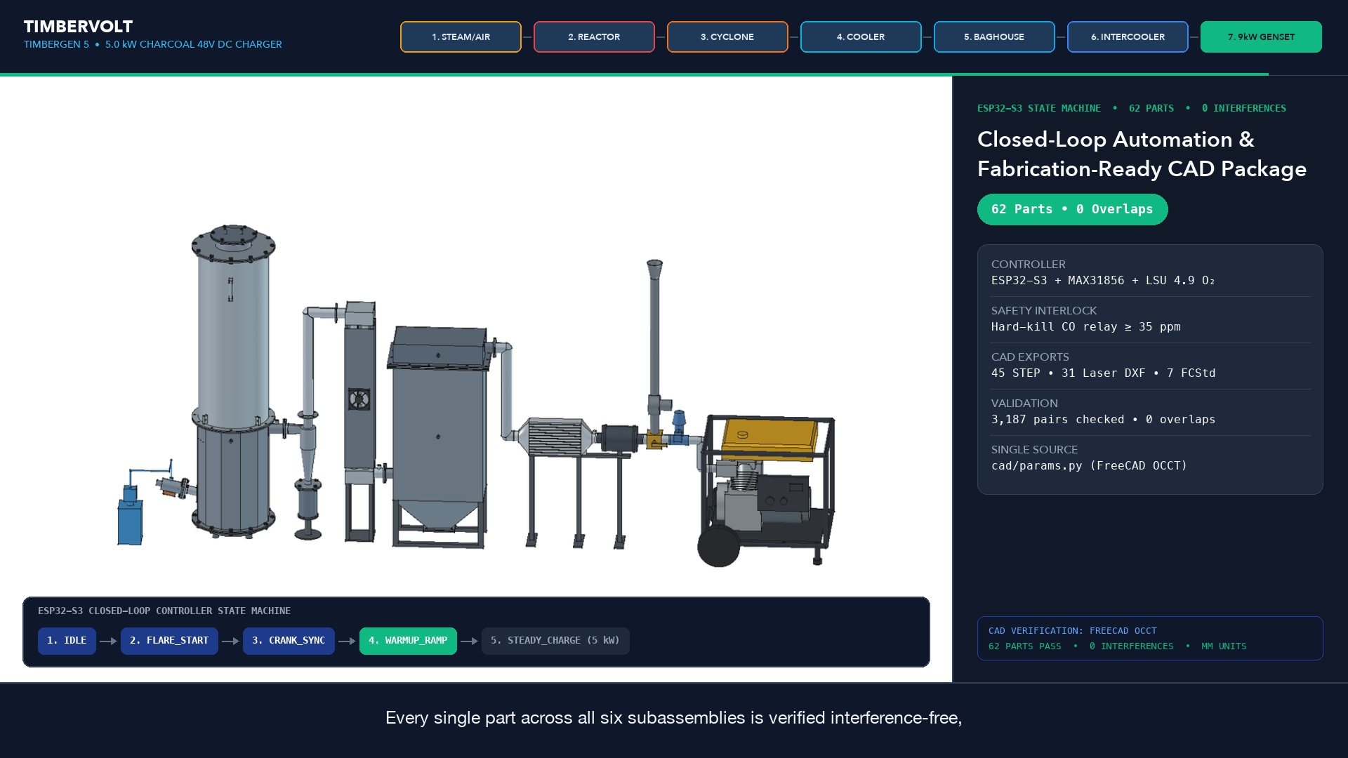
| Sensor / Actuator | Nominal Target | Hard Trip Limit | Operational Meaning & Control Action |
|---|---|---|---|
T_noz (Core) | 1,000 – 1,150 °C | > 1,350 °C | Regulated via P_h2o water drip (8.5–14.2 mL/min) to prevent clinkering. |
T_rx_out (Exit) | 250 – 350 °C | > 420 °C | Steady climb above 370 °C indicates low charcoal bed; prepare to refuel. |
T_bag_in (Filter) | 120 – 140 °C | > 185 °C | Held by Stage 1 PWM fan (avoids wet condensation <110 °C & Nomex scorch). |
T_eng_in (Intake) | 35 – 55 °C | > 75 °C | Dense, cool syngas leaving Stage 2 intercooler & pleated safety filter. |
dP_rx / dP_bag | 2.8–4.0 / 0.5–3.5 inH2O | dP_bag > 14 inH2O | Measures bed permeability and Nomex filter dust cake buildup. |
Lambda (LSU 4.9) | λ = 1.02 | Open-Loop Fault | Auto-tracked by V_air NEMA 17 stepper + 5:1 planetary gearbox. |
CO_Loop (Ambient) | 0 ppm | ≥ 35 ppm | Hard-wired NC safety relay: instant magneto kill & intake isolation. |
0 A and switch the DC load breaker OFF.P_h2o water drip stops immediately while the engine idles unloaded for a 30-second dry purge to clear moisture from the steam pre-chamber, NBSiC nozzle, and char bed.T_rx_out < 60 °C before servicing or refilling.
7. FAULT_LATCH)| Fault / Alarm | Unit | Automatic Controller Action | Root Cause & Required Recovery Steps |
|---|---|---|---|
| CO_Loop ≥ 35 ppm | TimberGen 5 | Instant magneto ground, P_h2o OFF, air solenoid closed, fault latched. |
Evacuate to fresh air immediately. Once cool, vacuum-test (-25 inH2O) all bolted flanges, floating nozzle gland, and 3-way flare diverter before restarting. |
| T_noz > 1,350 °C | TimberGen 5 | Chargeverter load shed, fault latch shutdown. | Check empty P_h2o distilled water tank, kinked BPT peristaltic tubing, or clogged evaporator drip needle. Refill, prime pump, and clear latch. |
| T_bag_in > 185 °C | TimberGen 5 | Immediate shutdown to protect PTFE-glazed Nomex filter bags. | Verify Stage 1 Pre-Cooler 120 mm PWM fan power/RPM; check for low char level / bed channeling (T_rx_out > 420 °C). Inspect bags before next run. |
| dP_bag > 14 inH2O | TimberGen 5 | Controlled shutdown & filter-blinding alert. | Cool unit, unclamp Dual Size #2 Nomex Baghouse cover, gently shake/vacuum ash cake off outside-in bags, and empty lower baghouse dust hopper. |
| T_glycol_out > 92 °C | TimberKiln 25 | Pump_glycol 100% to dump loop, V_air_sec throttled, high-temp alarm. |
Thermal storage tank saturated or trapped air in glycol loop. Verify pump flow, bleed air at top 1" NPT tree, and confirm dump radiator fan operation. |
| P_glycol > 3.0 bar | TimberKiln 25 | Mechanical brass PRV relieves pressure. | Check expansion tank pre-charge (~1.5 bar cold) and verify no shut isolation valves in the hydronic return line. |
| Flame_UV Drop | TimberKiln 25 | Auto-igniter pulses; cuts V_air_sec if unlit after timeout. |
Normal at end of pyrolysis (T_firebox < 450 °C → enters Cooldown). If mid-batch, clean UV sight lens on -X boss and check kindling bed temperature. |
| Service Interval | Unit | Required Maintenance & Inspection Tasks |
|---|---|---|
| After Every Batch | TimberKiln 25 | Empty 48V micro-cyclone dust catch jar; brush top 640 mm braided graphite lid gasket; inspect corrugated NBR boot hose clamps for dust-tight seal. |
| After Every Run | TimberGen 5 | Empty 78 mm Stairmand hot cyclone sealed catch pot (~1 L fine fly ash); open & close Stage 2 intercooler 1/4" NPT condensate drain petcock; top off P_h2o distilled water reservoir. |
| Every 5 Batches | TimberKiln 25 | Unbolt -Y hydronic jacket soot-cleanout inspection hatch and brush fly ash off the 14.5 m spiral-finned 304SS coil; remove front trommel inspection cover to verify 2.0 mm and 15.0 mm meshes are clear. |
| Every 5 Runs (~25–30 hrs) |
TimberGen 5 | Unbolt reactor bottom cleanout door and empty the 130 mm (6.4 L) ash cup; visually inspect the precast alumina liner and 16 mm NBSiC nozzle tip for slag; shake/inspect Dual Size #2 Nomex bags and inline pleated safety backstop element. |
| Every 100 hrs / Seasonal |
Both | Check Belleville disc spring compression & 6 mm ceramic fiber rope in TimberGen 5's floating nozzle gland; inspect TimberKiln 25's 4140 hardened crusher teeth & 14 mm nip-gap slide locks; change 459cc genset engine oil & check spark plug; verify glycol freeze protection & personal CO monitor bump-test calibration. |
110 kg Split Cordwood (20% MC) → TimberKiln 25 → ~80 kWhth Hot Water/Glycol + ~3 kg Biochar Fines + ~24 kg Engine-Grade Charcoal (6–15 mm) → TimberGen 5 → ~30 kWhe Net 48V DC (6.0 hrs @ 5.0 kW / 96 A).